In this experiment you will observe how a resistor affects the brightness of an LED. Resistors are used in circuits to control the amount of current flowing through components.
By changing the resistor value in a simple LED circuit, you can directly observe how current influences LED brightness.
Understand how resistors control current in a circuit and how changing resistance affects LED brightness.
Connect the resistor in series with the LED and battery.
Battery positive → resistor → LED → battery negative.
The resistor limits the amount of current that flows through the LED.
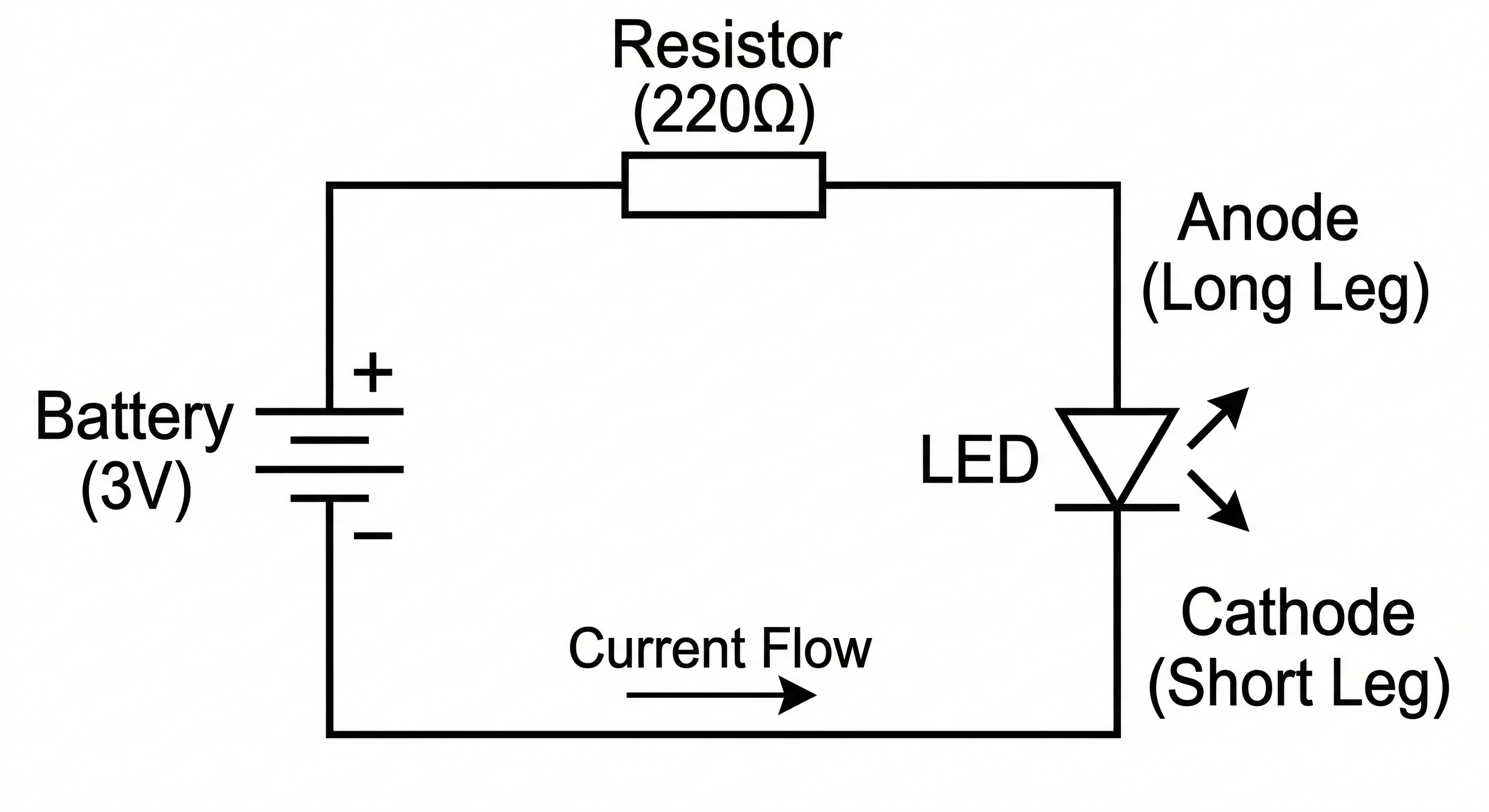
Circuit Diagram showing a LED Brightness Control with Resistor.
The following layout shows how the circuit can be built on a breadboard.
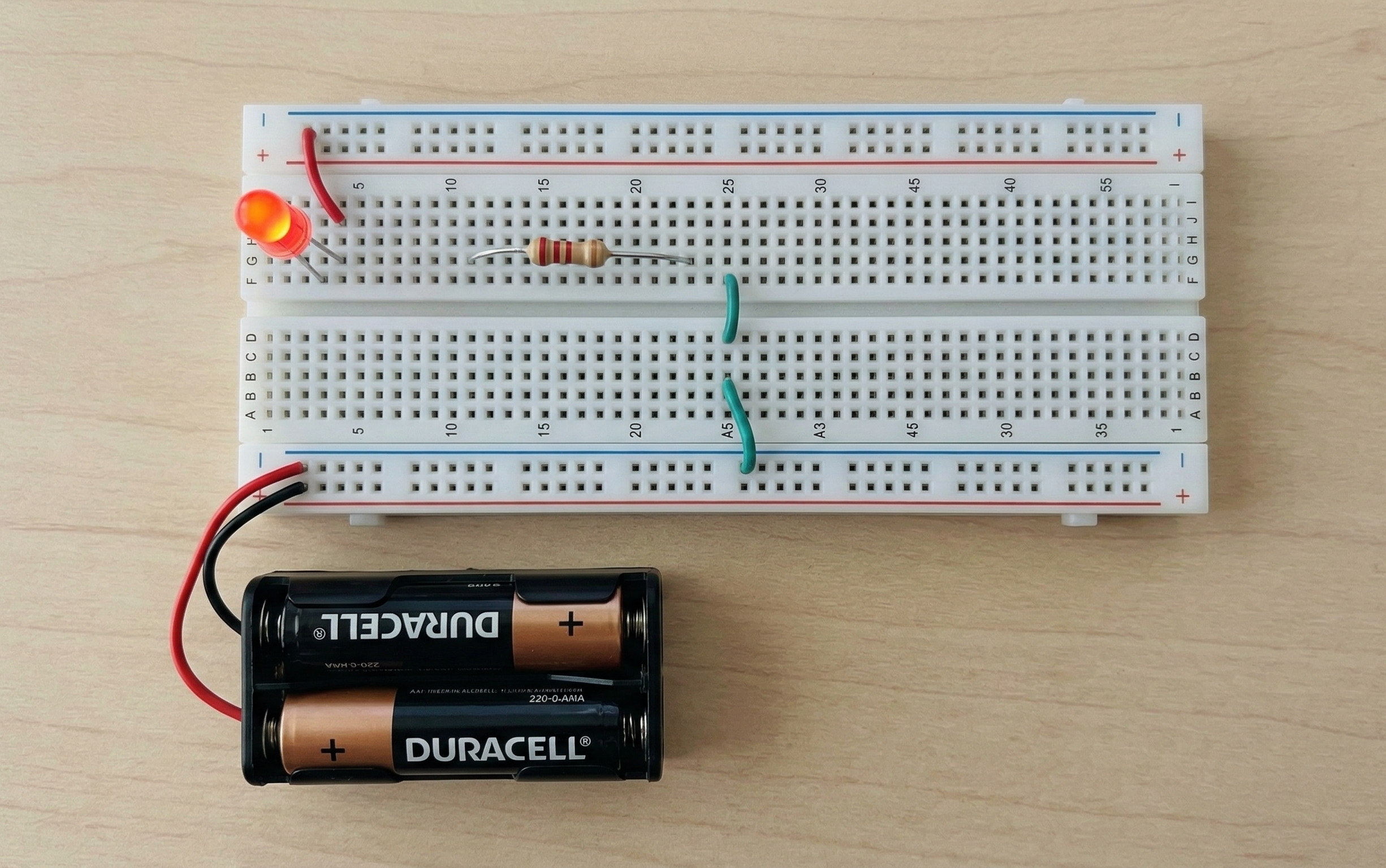
Practical breadboard wiring for the LED Brightness Control with Resistor experiment. Also swap the battery terminal if LED not turn on.
When a lower value resistor is used, more current flows through the LED and the LED appears brighter.
When a higher value resistor is used, the current decreases and the LED becomes dimmer.
Resistors limit the flow of electric current in a circuit. According to Ohm's Law, the current flowing through a circuit decreases when resistance increases.
Since LED brightness depends on the current passing through it, increasing resistance reduces brightness while decreasing resistance increases brightness.
Always use a resistor when connecting LEDs to a power source. Without a resistor, too much current may damage the LED.