This experiment shows how an LED can be made to blink automatically using a simple electronic timing circuit. By building this circuit, you will learn how electronic components can control time and create repeating signals.
LED flashers are used in many real devices such as indicators, alarms, warning lights and signal systems.
Understand how a timing circuit works and how a 555 timer IC can be used to make an LED turn on and off repeatedly.
The 555 timer IC is configured in astable mode, which means it continuously switches between HIGH and LOW output states.
This switching output causes the LED to turn on and off repeatedly, creating a flashing effect.
The resistors and capacitor connected to the timer control how fast the LED flashes.
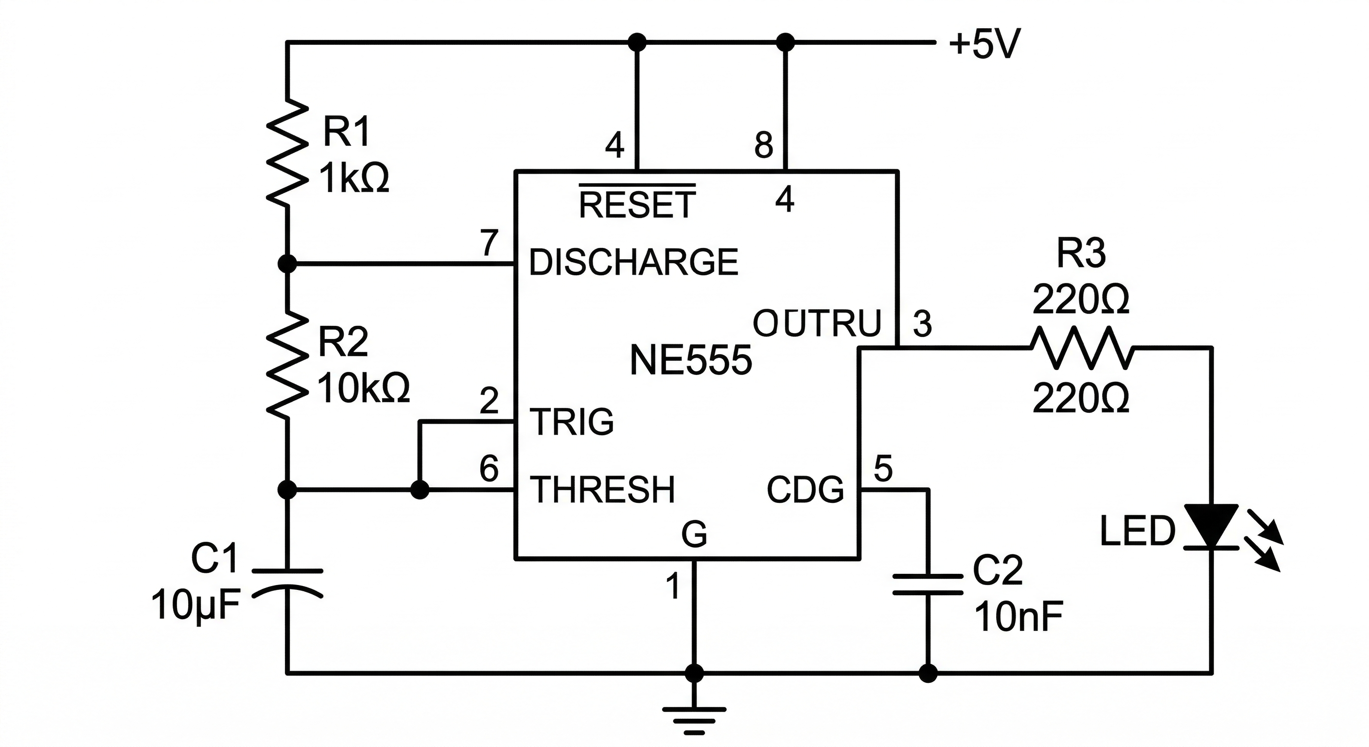
Circuit Diagram showing a LED Flasher Circuit.
The LED will turn on and off repeatedly at a steady speed. The blinking speed depends on the resistor and capacitor values used in the timing circuit.
The 555 timer charges and discharges the capacitor through resistors in a repeating cycle.
As the capacitor voltage rises and falls, the internal circuitry of the timer switches the output between HIGH and LOW states.
This switching output drives the LED, causing it to flash continuously.
Only use low-voltage power supplies such as batteries or regulated DC supplies for this experiment.