This experiment helps you understand the difference between series circuits and parallel circuits. By connecting LEDs in different ways, you will observe how electricity flows through each circuit configuration.
Understanding the difference between series and parallel connections is essential because almost all real electronic systems use a combination of these two circuit types.
Observe how current flows in series and parallel circuits and understand how the behavior of LEDs changes depending on how they are connected.
In a series circuit, components are connected one after another in a single path. The same current flows through every component in the circuit.
Connect the LEDs in series with the battery so the current must pass through both LEDs in sequence.
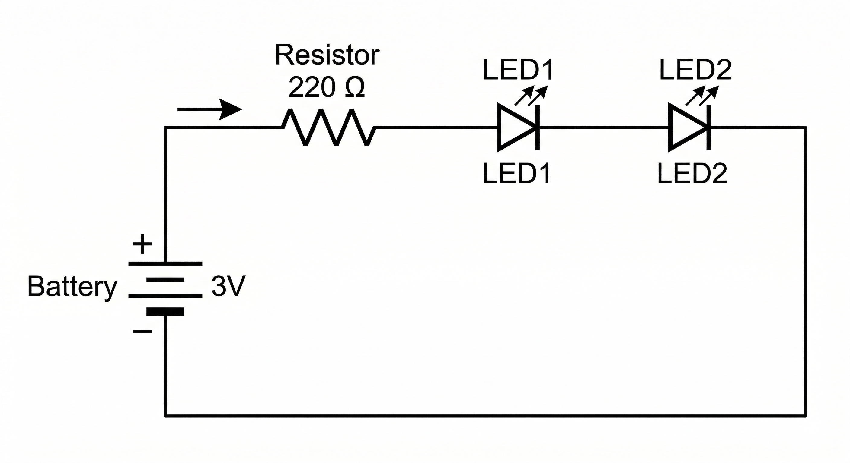
Series Circuit Diagram showing a Series vs Parallel LED Circuit.
Both LEDs may light, but they may appear dimmer compared to a single LED circuit. This happens because the voltage from the battery is shared across both LEDs.
In a parallel circuit, each component is connected directly across the power source. Each branch receives the same voltage from the battery.
Connect both LEDs so that each LED has its own path to the battery terminals.
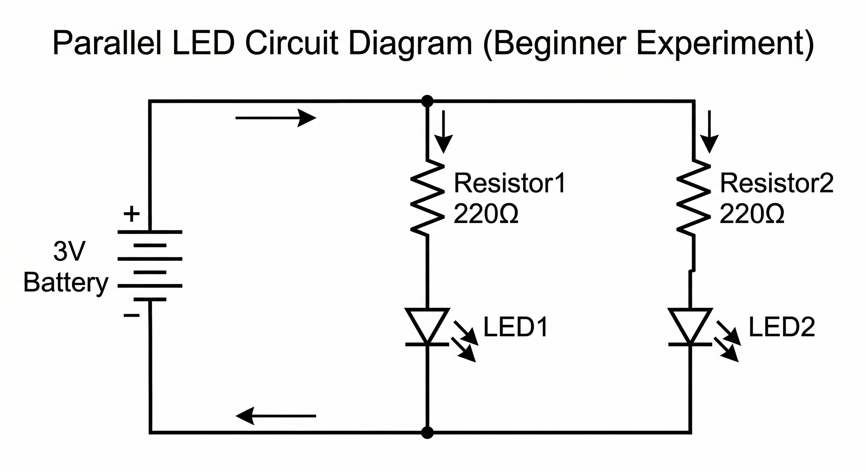
Parallel Circuit Diagram showing a Series vs Parallel LED Circuit.
Both LEDs should light with similar brightness. Even if one LED is disconnected, the other LED will continue to glow because each LED has its own path for current.
In a series circuit, the voltage is divided among the components, and the same current flows through each one. If one component is removed, the circuit becomes open and current stops flowing.
In a parallel circuit, each component is connected directly to the power source, so each branch receives the same voltage. If one branch stops working, the others continue operating.
Always use a resistor with LEDs when using power supplies higher than small coin cell batteries.