A breadboard is one of the most useful tools in electronics. It allows you to build and test circuits without soldering components together.
In this experiment, you will learn how the internal connections of a breadboard work and how electronic components can be connected using it.
Understand how a breadboard is structured and how components and wires can be connected to build simple electronic circuits.
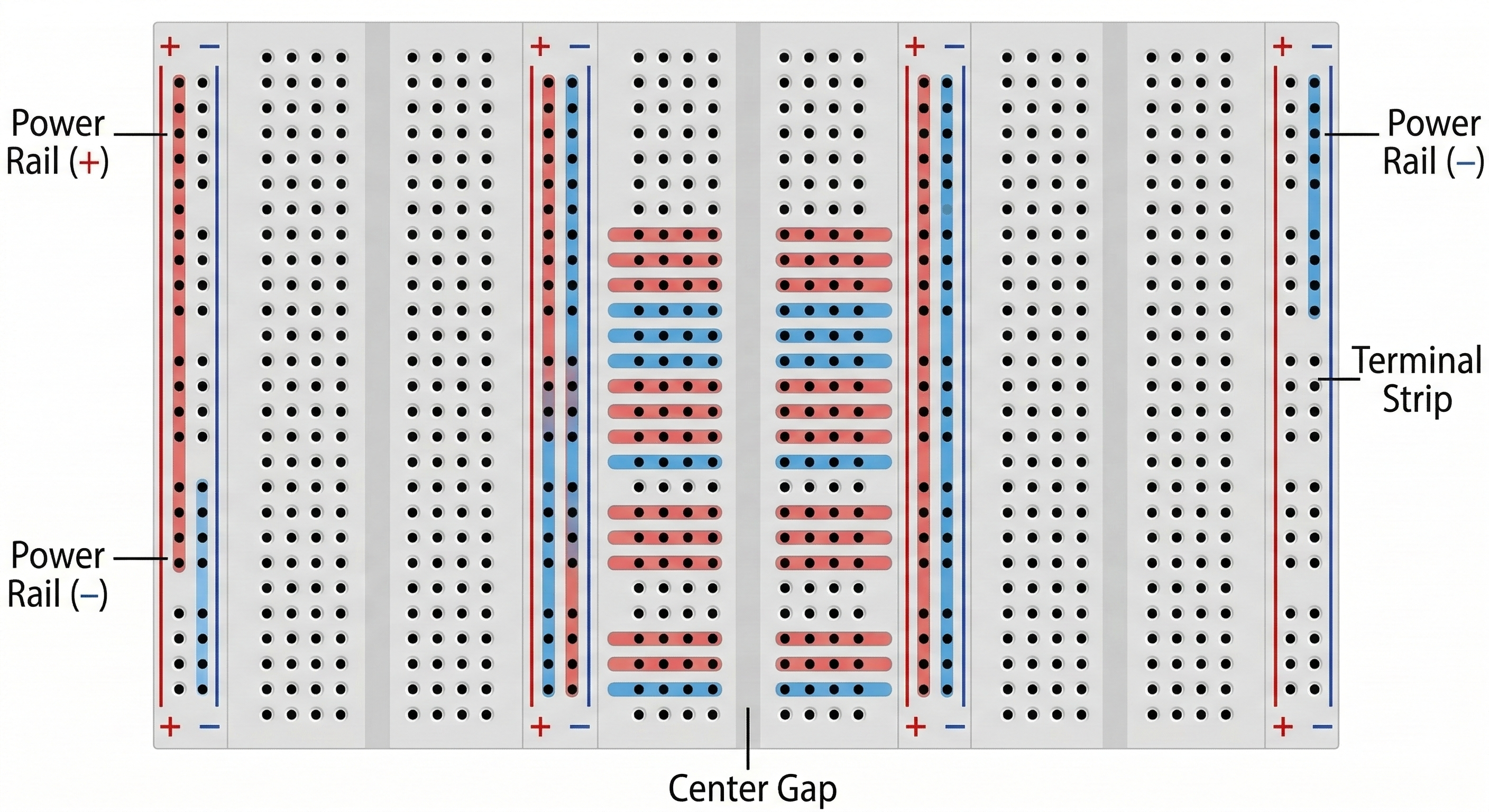
A breadboard contains rows and columns of internally connected metal strips that allow components to be connected together.
A breadboard contains rows and columns of internally connected metal strips that allow components to be connected together.
Most breadboards have three main sections:
The holes in each row of the terminal strip are electrically connected internally.
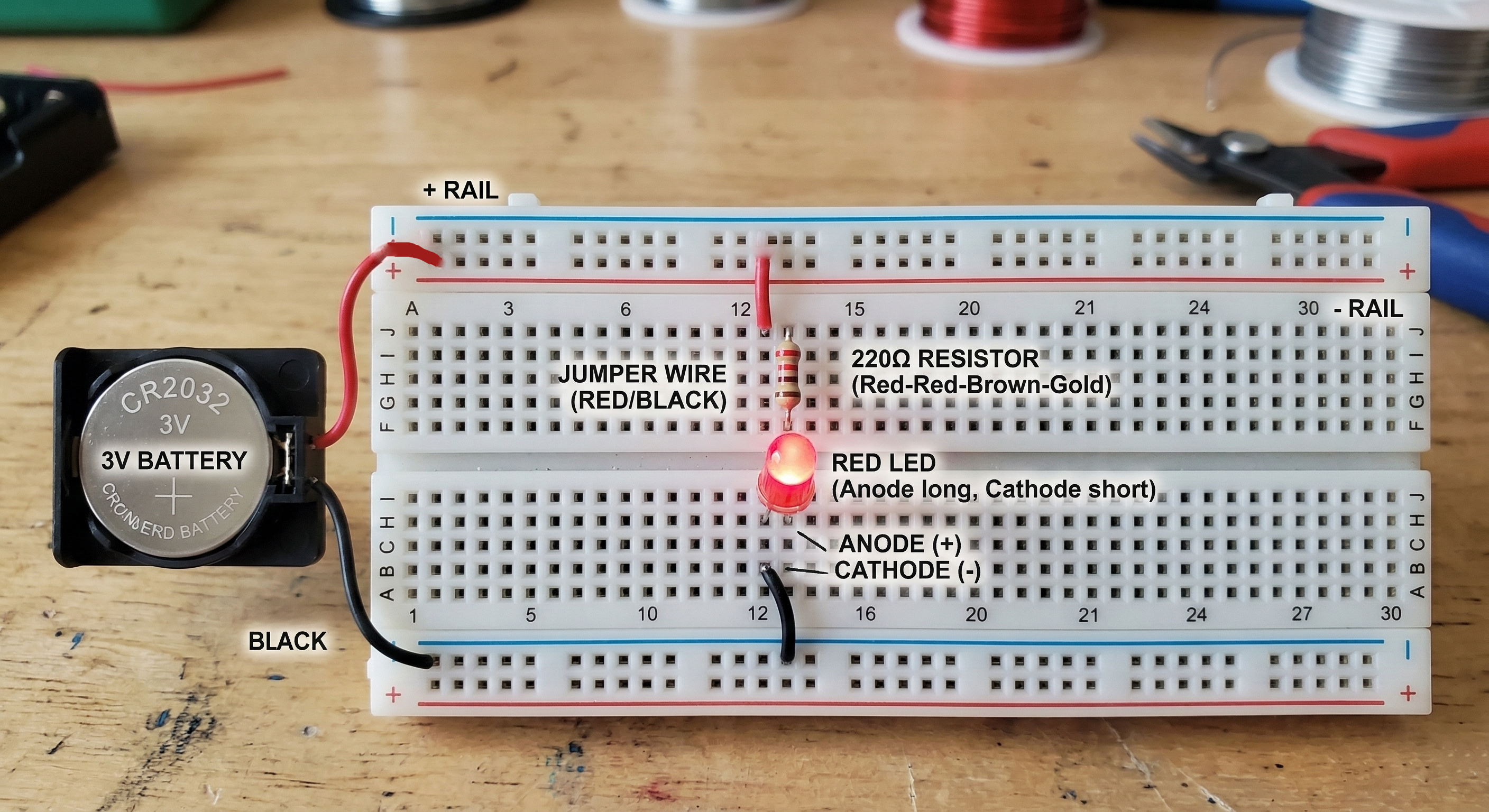
The following layout shows how the LED, resistor and battery can be connected on the breadboard.
When the circuit is connected properly, the LED should light up.
This shows that the breadboard connections are allowing current to flow through the components without needing soldering.
Inside the breadboard, metal strips connect certain holes together. When components are inserted into those holes, they become electrically connected through these internal metal contacts.
This allows you to quickly build, test and modify circuits during learning and prototyping.
Breadboards are designed for low voltage experiments. Avoid using high voltage or mains electricity on a breadboard.